3DPDiffWrist: 3D printed differential wrist
The idea was to build a simple differential wrist using almost 3D printed parts, and that could be used as base for other mechanisms. A robot arm, maybe. ;)
Run it for sufficient long time, plastic gears needs some breaking in. Have fun, most of all!
This is version zero, take it with a pinch of salt!
Comments and suggestions are always welcomed!
For academic purposes quote this project using the Zenodo's reference DOI:
Charters, Tiago, (2026). 3DPDiffWrist: 3D printed differential wrist. Zenodo. https://doi.org/10.5281/zenodo.23287814
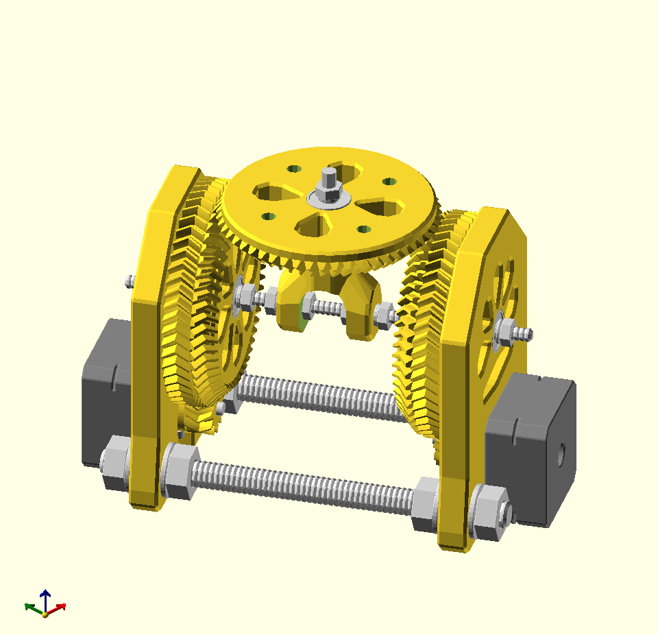
I'll try and make the building instructions complete, any error or lack of clarity please contact me (see bottom of page for my email).
So, here goes.
Printed parts
| File name | Qty | Render | Photo |
|---|---|---|---|
| biggear.stl | 2 |  |
 |
| smallgear.stl | 2 |  |
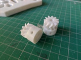 |
| topgear.stl | 1 |  |
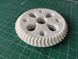 |
| plate.stl | 2 |  |
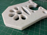 |
| center.stl | 1 |  |
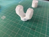 |
| washer.stl | 2 |  |
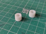 |
20%, 0.2mm layer height, no supports.
STL parts are oriented the right way i.e. oriented to be printed (see pics above).
Vitamins
| Qty | size | Description |
|---|---|---|
| 10 | 5x5x16mm | bearings |
| 10 | 10mm M3 | screws |
| 2 | M3 | nuts |
| 8 | M3 | washer |
| 2 | 200m M5 | threaded rod |
| 1 | 40mm M5 | hex screw |
| 16 | M5 | nuts |
| 32 | M5 | washer |
| 2 | 200m M10 | threaded rod |
| 8 | M10 | nuts |
| 8 | M10 | washer |
Electronics
| Quantity | Description | Photo |
|---|---|---|
| 2 | NEMA 17 | 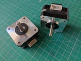 |
| 1 | Arduino UNO | 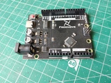 |
| 1 | GRBL shield | 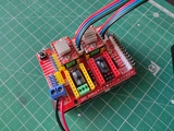 |
| 2 | A4988 driver | 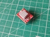 |
| 1 | 12V power source | 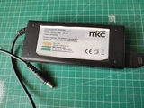 |
| 1 | DC plug | 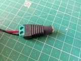 |
or anything equivalent.
Some math
Depending on the NEMA motors that you have you may have to recalculate
the stepsPer/Degree value. My
motors are 1.8° steppers which have 360/1.8=200 steps/rev e.g. for
0.9° steppers one has 400 steps/rev.
NEMA 17 steps per revolution = 200
microsteps = 16
bigear teeth = 53
topgear teeth = 53
small gear teeth = 11

number of steps per revolution (360 degrees) = 200*16*53/11
stepsPer/Degree = 200*16*53/(11*360) = 42.82828282828282...
This will go to GRBL defining steps/mm. See GRBL setup variables $100 and $101 below.
How does it work?
When motors rotate in opposite directions at the same speed: the input gears turn against each other, driving the differential top gear to pivot around its central cross-pin. This causes the wrist assembly to pitch up or down.
When motors rotate in the same direction at the same speed: both input gears rotate in unison, carrying the top gear around with them without turning the internal differential pin. This causes the wrist assembly to roll rotate on its axis.
When motors rotate at different speeds: the movement becomes a combined simultaneous pitch and roll.
So X is the value of the pitch angle and Y refers to the roll angle.
GCODE example
G0 X10 ;pure pitch
G0 Y10 ;pure roll
G0 X-10 Y3 ;pitch and roll combined
GRBL firmware
Using GRBL but any other will work. When using GRBL enable COREXY (see config.h)
GRBL 1.1h parameters
Grbl 1.1h ['$' for help]
$0 = 10    (Step pulse time, microseconds)
$1 = 255    (Step idle delay, milliseconds)
$2 = 0    (Step pulse invert, mask)
$3 = 1    (Step direction invert, mask)
$4 = 0    (Invert step enable pin, boolean)
$5 = 0    (Invert limit pins, boolean)
$6 = 0    (Invert probe pin, boolean)
$10 = 1    (Status report options, mask)
$11 = 0.010    (Junction deviation, millimeters)
$12 = 0.002    (Arc tolerance, millimeters)
$13 = 0    (Report in inches, boolean)
$20 = 0    (Soft limits enable, boolean)
$21 = 0    (Hard limits enable, boolean)
$22 = 0    (Homing cycle enable, boolean)
$23 = 0    (Homing direction invert, mask)
$24 = 25.000    (Homing locate feed rate, mm/min)
$25 = 500.000    (Homing search seek rate, mm/min)
$26 = 250    (Homing switch debounce delay, milliseconds)
$27 = 1.000    (Homing switch pull-off distance, millimeters)
$30 = 1000    (Maximum spindle speed, RPM)
$31 = 0    (Minimum spindle speed, RPM)
$32 = 0    (Laser-mode enable, boolean)
$100 = 42.828    (X-axis travel resolution, step/mm)
$101 = 42.828    (Y-axis travel resolution, step/mm)
$102 = 250.000    (Z-axis travel resolution, step/mm)
$111 = 6000.000    (Y-axis maximum rate, mm/min)
$110 = 6000.000    (X-axis maximum rate, mm/min)
$112 = 600.000    (Z-axis maximum rate, mm/min)
$120 = 36000.000    (X-axis acceleration, mm/sec^2)
$121 = 36000.000    (Y-axis acceleration, mm/sec^2)
$122 = 10.000    (Z-axis acceleration, mm/sec^2)
$130 = 200.000    (X-axis maximum travel, millimeters)
$131 = 200.000    (Y-axis maximum travel, millimeters)
$132 = 200.000    (Z-axis maximum travel, millimeters)
Assembly
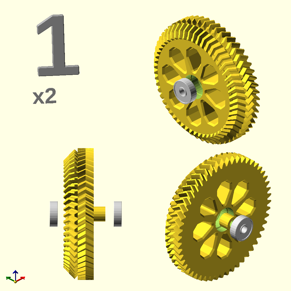
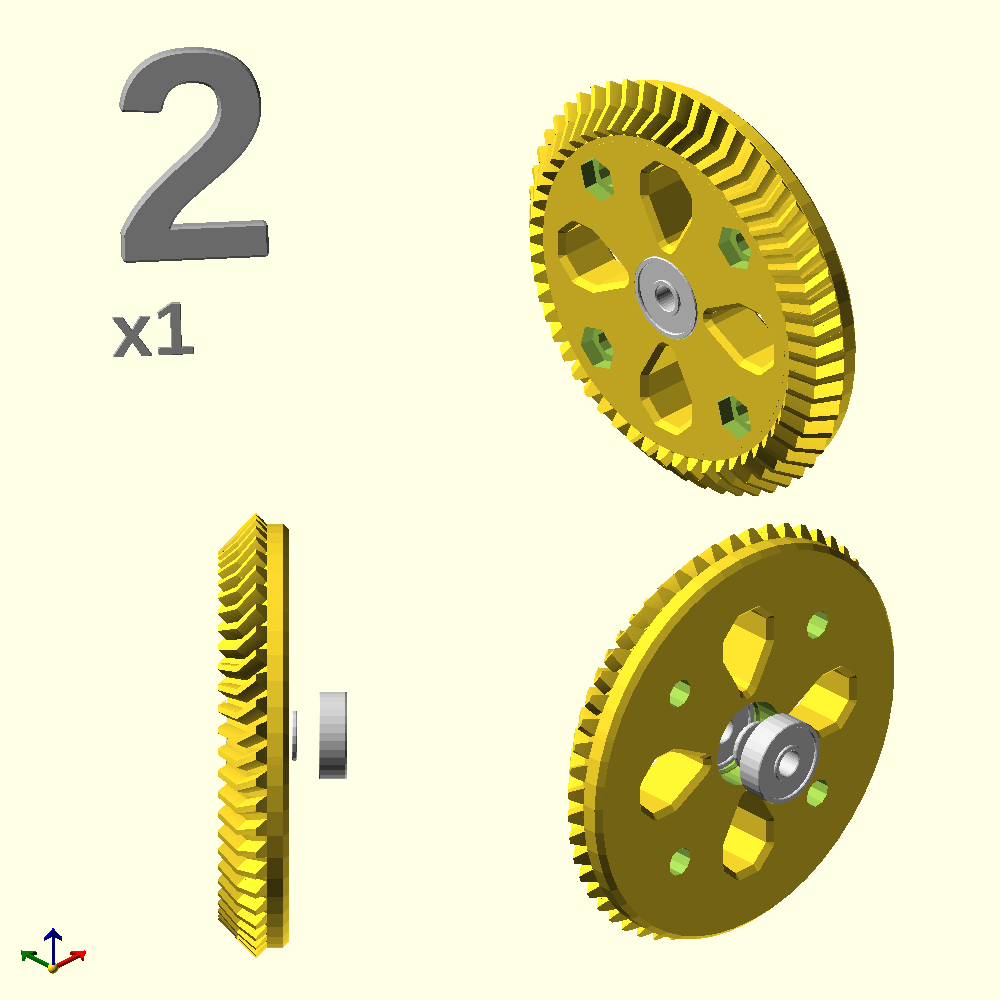
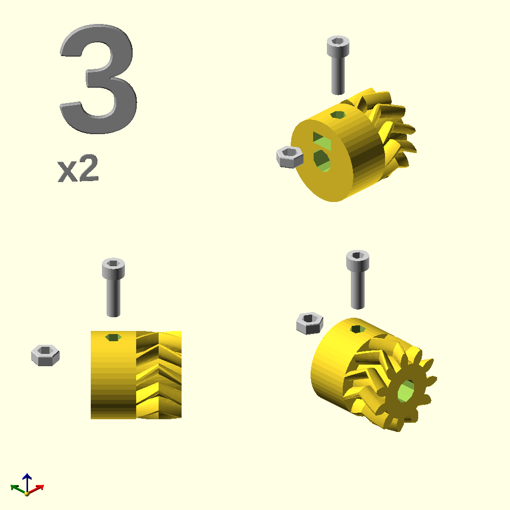
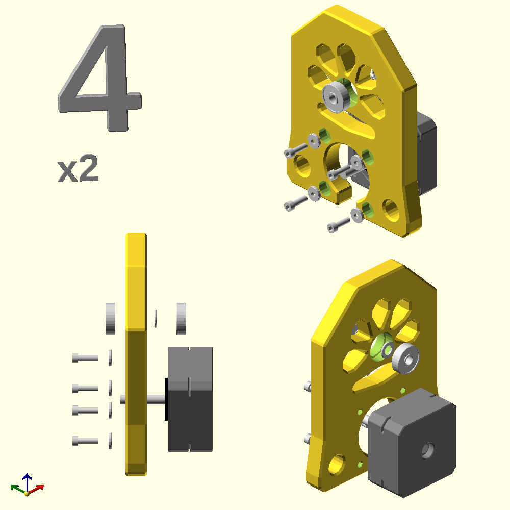
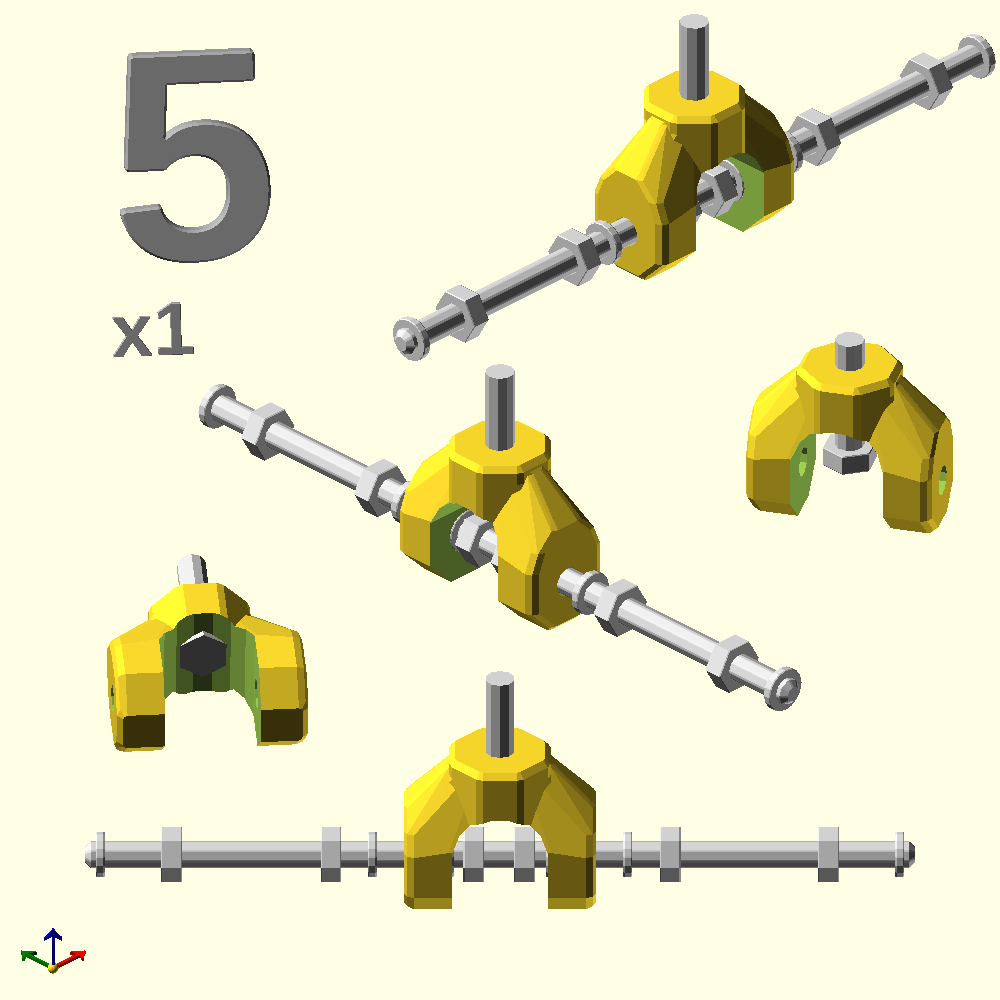
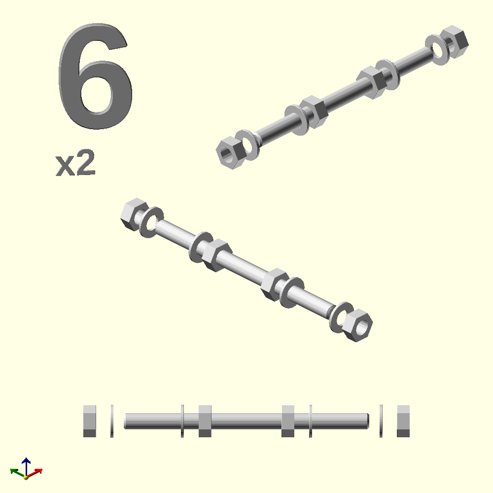
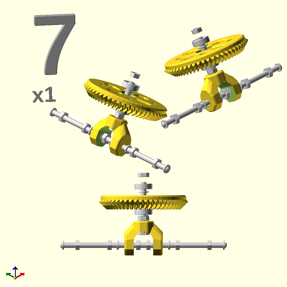
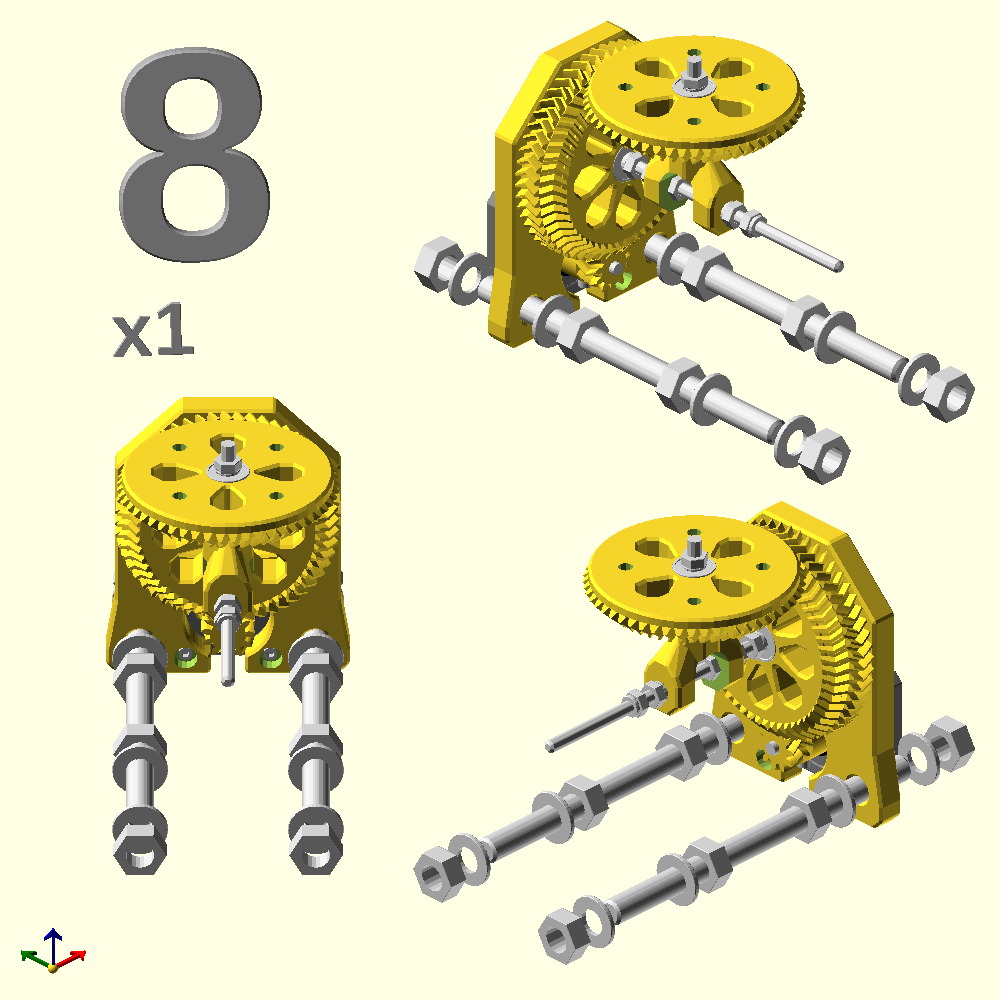
A 12 steps montage is given at the bottom of this page. Here's one by one for clarity.
Note that plates and gears should be parallel, take your time to check all nuts, spaces between them. Run it for sufficient long time, plastic gears needs some breaking in. Have fun, most of all!
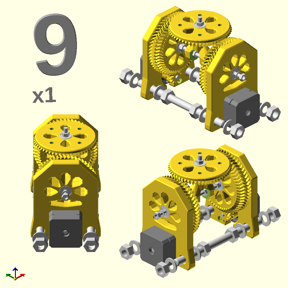

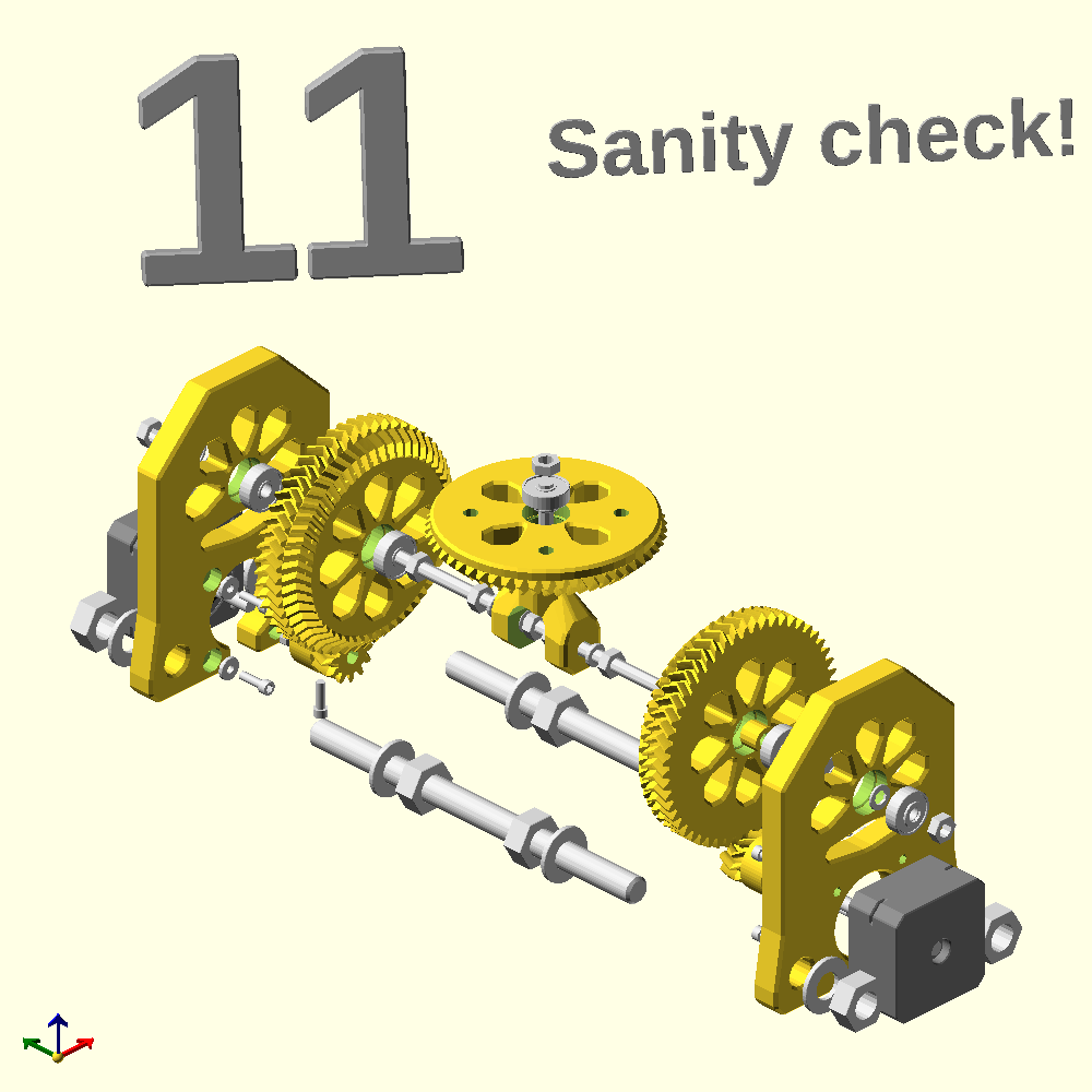
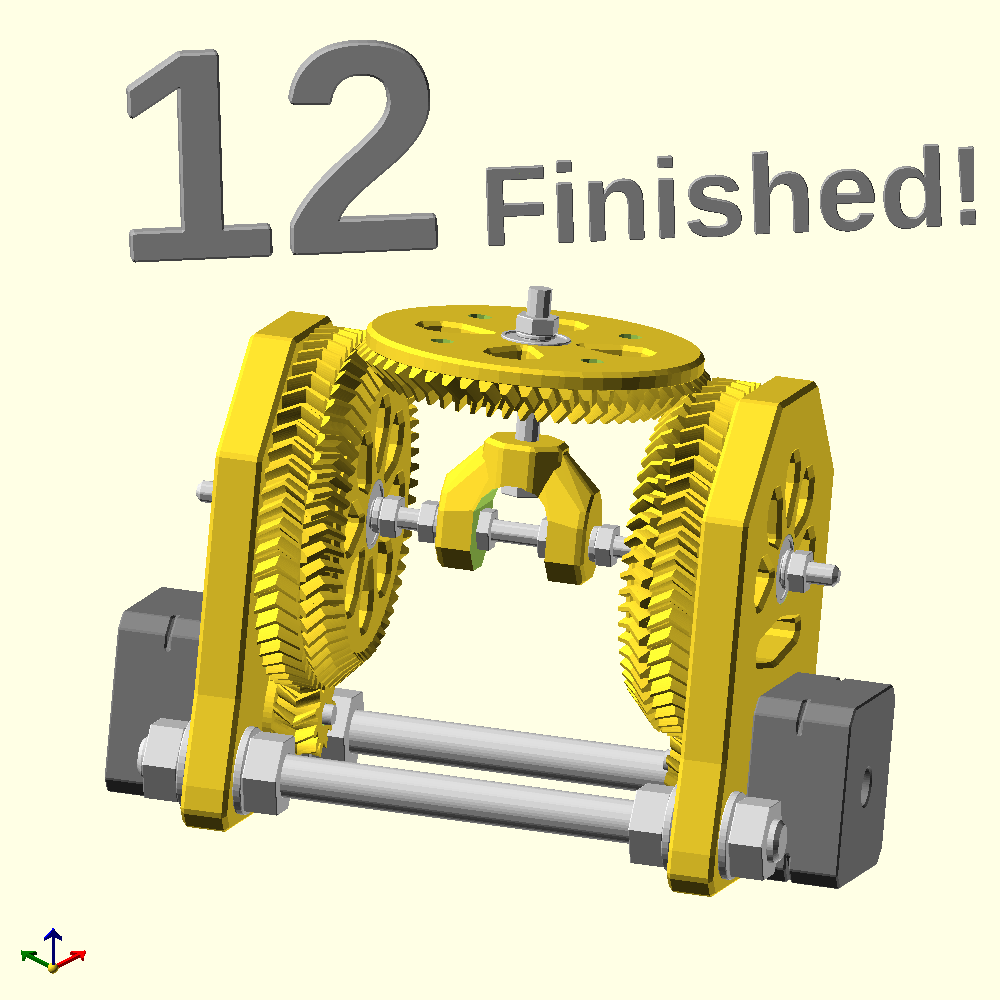
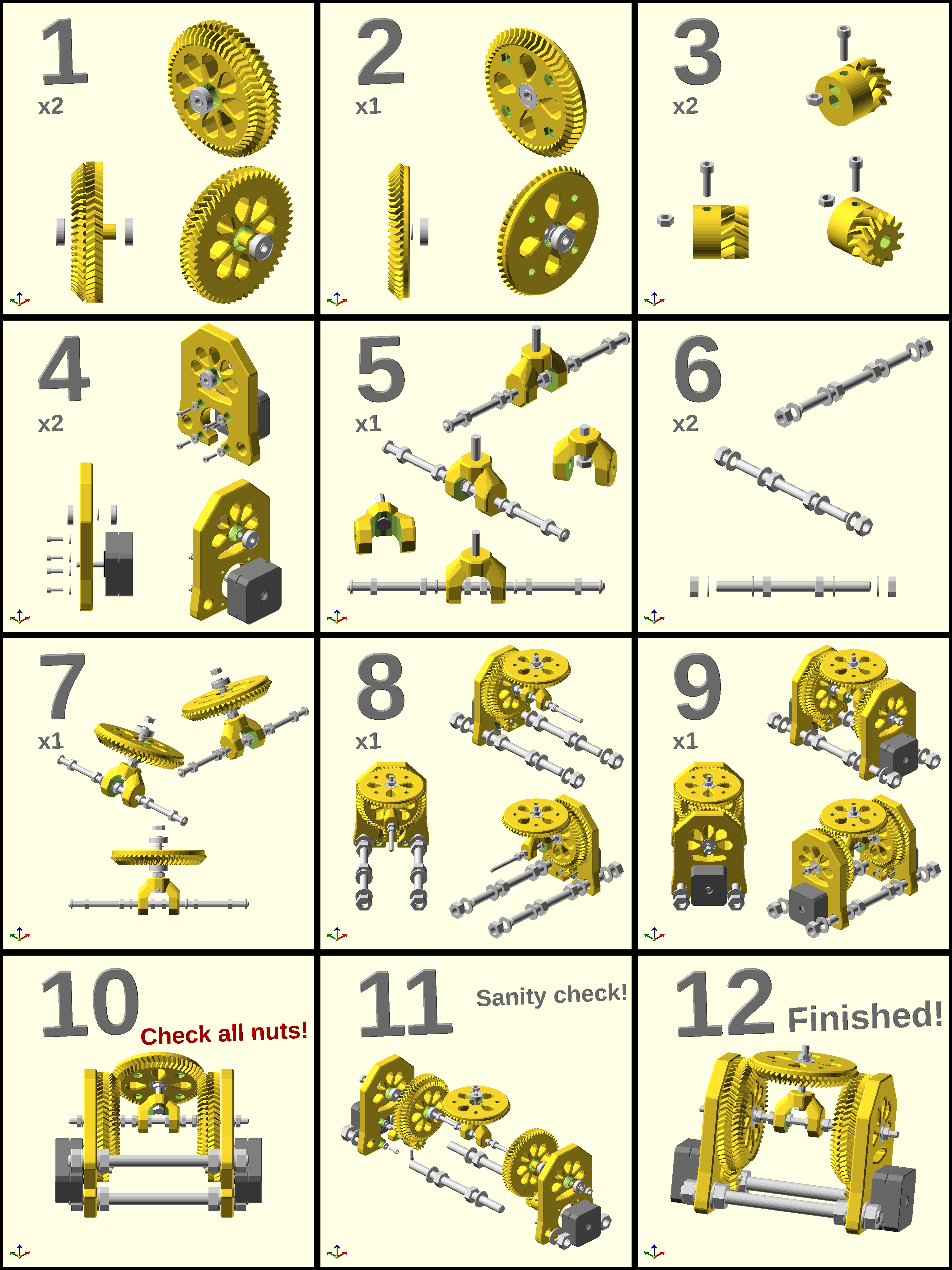
Have fun, and Happy hacking!
Note that you can, and should, use my work under the Attribution-ShareAlike 4.0 International.
You can also find this project on Printables: https://www.printables.com/@tiagocharters/
Created: 09-10-2026 [22:18]
Last updated: 10-10-2026 [22:57]
For attribution, please cite this page as:
Charters, T., "3DPDiffWrist: 3D printed differential wrist": https://nexp.pt/diffwrist.html (10-10-2026 [22:57])
(cc-by-sa) Tiago Charters - tiagocharters@nexp.pt
